Volume flow rate measuring unit VMRK
VMRK with control component ELAB TCU3
VMRK with control component ELAB TCU3
Plastic circular volume flow rate measuring devices for recording or monitoring the
volume flow rate
Optional equipment and accessories
Variants
Parts and characteristics
Attachments
Effective pressure transducer for static pressure measurements
Accessories
Construction features
Materials and surfaces
Standards and guidelines
Fulfils the hygiene requirements of
Casing leakage
Closed damper blade air leakage
Maintenance

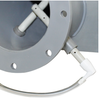
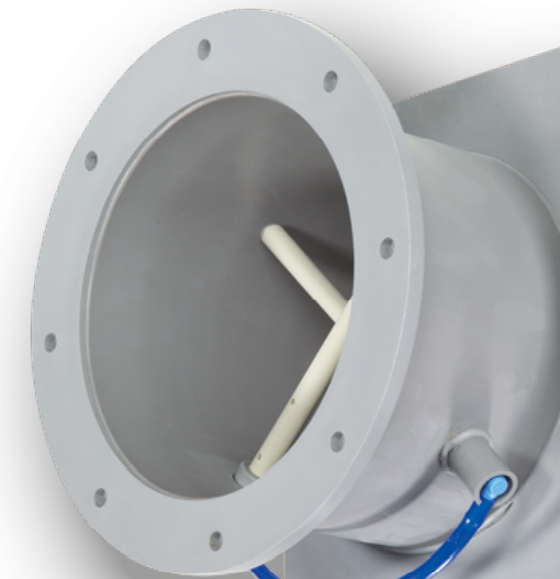
1: Effective pressure sensor
2: Measuring transducer
3: Casing
1: Effective pressure sensor
2: Measuring transducer
3: Casing
The volume flow rate measuring unit is fitted with an effective pressure sensor for measuring the volume flow rate. The effective pressure is either measured and evaluated manually, or transformed into an electrical signal by a measuring transducer (effective pressure transducer).
| Nominal sizes | 125 – 400 mm |
| Volume flow rate range | 20 – 1660 l/s or 70 – 5978 m³/h |
| Maximum differential pressure | 1000 Pa |
| Effective pressure range | Approx. 5 – 260 Pa* |
| Measurement accuracy | 5 – 10 % |
| Operating temperature | 10 to 50 °C |
* 260 Pa with nominal flow rate
Die Schnellauslegung gibt einen guten Überblick über die Volumenstrommessbereiche, Messgenauigkeiten und die C-Werte der einzelnen Nenngrößen. Berechnung der Volumenströme aus den gemessenen Wirkdrücken bei Ausführung ohne Anbauteile siehe in Abschnitt „Produktdetails“.
Volume flow rate ranges
Attachment: XTS, BTS, ELAB or no attachment
| NS | qv [l/s] | qv [m³/h] | K value [l/s] | K value [m³/h] | Δqv [±%] |
|---|---|---|---|---|---|
| 125 | 20 | 70 | 8,6 | 31,0 | 10 |
| 125 | 138 | 499 | 8,6 | 31,0 | 6 |
| 160 | 34 | 122 | 15,1 | 54,0 | 10 |
| 160 | 243 | 876 | 15,1 | 54,0 | 5 |
| 200 | 55 | 196 | 24,3 | 87,5 | 10 |
| 200 | 391 | 1410 | 24,3 | 87,5 | 5 |
| 250 | 85 | 306 | 38,0 | 136,8 | 10 |
| 250 | 612 | 2205 | 38,0 | 136,8 | 5 |
| 315 | 139 | 500 | 62,0 | 223,2 | 10 |
| 315 | 999 | 3598 | 62,0 | 223,2 | 5 |
| 400 | 231 | 830 | 103,0 | 370,8 | 10 |
| 400 | 1660 | 5978 | 103,0 | 370,8 | 5 |
Note:
Specification text
Circular volume flow rate measuring device made of PPs plastic, for variable and constant air volume systems, suitable for extract air, available in 6 nominal sizes. For manual volume flow rate measurement or for the permanent monitoring of the actual value signal. High measurement accuracy of volume flow rates (even with bend R = 1D). Ready-to-commission unit which consists of the mechanical parts and an optional pressure transducer. Slide-out sensors allow for easy cleaning
Each unit contains an averaging effective pressure sensor for volume flow rate measurement. Effective pressure sensor with 3 mm measuring holes, hence resistant to contamination.
Meets the hygiene requirements of EN 16798, Part 3, of VDI 6022, Sheet 1, and of DIN 1946, Part 4.
| VMRK | – | FL | / | 160 | / | GK | / | XTS | / | 0 |
| | | | | | | | | | | | | |||||
| 1 | 2 | 3 | 4 | 5 | 6 | |||||
| Duct connection | Flanges on both ends |
| Nominal size | 315 mm |
| Accessories | Matching flange |
| Attachments (effective pressure transducer) | Static effective pressure transducer XTS |
| Actual value signal | 0 – 10 V DC |
| VMRK | – | FL | / | 160 | / | GK | / | ELAB | / | EC | – | E0 | / | UMZ |
| | | | | | | | | | | | | | | | | |||||||
| 1 | 2 | 3 | 4 | 5 | 6 | 7 | 8 |
| Duct connection | Spigot |
| Nominal size | 200 mm |
| Attachments | EASYLAB TCU3 |
| Equipment function | Extract air controller |
| External volume flow rate setting | Voltage signal 2 – 10 V DC |
| Expansion module | With expansion module EM-TRF, transformer for 230 V AC supply with expansion module EM-AUTOZERO, solenoid valve for automatic zero point correction |

Spigot
Standard construction
| Order code detail | Part | Material |
|---|---|---|
|
– |
Casing Effective pressure sensor |
Plastic, polypropylene (PPs), flame resistant |
Optional flange
| Order code detail | Part | Material |
|---|---|---|
|
FL |
Flange | Plastic, polypropylene (PPs), flame resistant |
Optional matching flange
| Order code detail | Part | Material |
|---|---|---|
|
GK |
Sea Matching flange |
Rubber, EPDM Plastic, polypropylene (PPs), flame resistant |
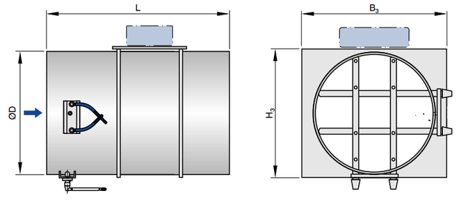


Dimensions and weights of VMRK (standard)
| NG | L | ∅D | B₃ | H₃ | kg |
|---|---|---|---|---|---|
| 125 | 394 | 125 | 195 | 145 | 0.8 |
| 160 | 394 |
160 | 230 | 180 | 1 |
| 200 | 394 |
200 | 270 | 270 | 1.4 |
| 250 | 394 |
250 | 320 | 270 | 2.4 |
| 315 | 394 |
315 | 385 | 335 | 4 |
| 400 | 394 |
400 | 470 | 420 | 5.8 |
Note:
Weights (~) apply only to VMRK without any attachments.
Note that an optional effective pressure transducer (attachment BTS, XTS or ELAB) may add to the weight.
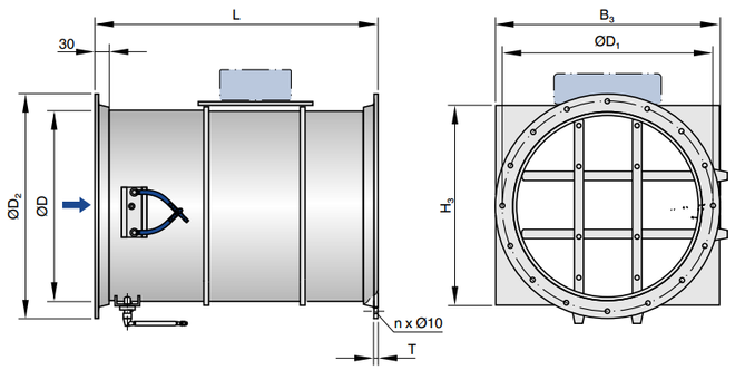
Dimensions and weights of VMRK-FL
| NG | L | ∅D | ∅D₁ | ∅D₂ | B₃ | H₃ | D | n | kg |
|---|---|---|---|---|---|---|---|---|---|
| 125 | 400 | 125 | 165 | 185 | 195 | 145 | 8 | 8 | 1.1 |
| 160 | 400 | 160 | 200 | 230 | 230 | 180 | 8 | 8 | 1.4 |
| 200 | 400 | 200 | 240 | 270 | 270 | 270 | 8 | 8 | 1.9 |
| 250 | 400 | 250 | 290 | 320 | 320 | 270 | 8 | 12 | 2.9 |
| 315 | 600 | 315 | 350 | 395 | 385 | 335 | 10 | 12 | 5 |
| 400 | 600 | 400 | 445 | 475 | 470 | 420 | 10 | 16 | 7 |
Note:
Weights (~) apply only to VMRK with flange and matching flange, but without any attachments.
Note that an optional effective pressure transducer (attachment BTS, XTS or ELAB) may add to the weight
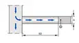
Space required for commissioning and maintenance
Sufficient space must be kept clear near any attachments to allow for commissioning and maintenance. It may be necessary to provide sufficiently sized inspection access openings. Product illustrations do not show any installation situation details. If an attachment requires a certain installation orientation, this is specified on a sticker on the product.
Space required
| Attachment | ① | ② | ③ |
|---|---|---|---|
|
Effective pressure transducer: BTS, XTS |
300 | 320 | 300 |
|
Effective pressure transducer: ELAB |
350 | 350 | 400 |
Space required for cleaning the sensor tubes
|
Nominal size
|
①
|
②
|
③
|
④
|
⑤
|
⑥
|
|
125 – 200 |
100 |
100 |
D |
– |
– |
– |
|
250 – 400 |
100 |
160 |
D |
100 |
160 |
D |
D: Casing diameter
Schematic illustration of required installation space
Note:
Weights apply only to VMRK with flange and matching flange, but without any attachments. Note that an optional effective pressure transducer (attachment BTS, XTS or ELAB) may add to the weight.
A bend with a curvature radius of at least 1D – without an additional straight duct section upstream of the volume flow rate measuring unit – has only a negligible effect on the volume flow rate accuracy.


Calculation conditions
Optional attachments for effective pressure transducers
| Attachment | Actual value | Effective pressure transducer | Manufacturer |
|---|---|---|---|
| Effective pressure transducer, static | |||
| XTS | 0 – 10 V or 2 – 10 V | integral | ① |
| BTS | 0 - 10 V or 2 - 10 V or MP bus or Modbus RTU or BACnet MS/TP | integral | ② |
| ELAB |
TROX plug and play communication system and 0 - 10 V or 2 - 10 V or with optional accessories: Modbus, BACnet, web server |
integral | ③ |
① TROX/Gruner, ② TROX/Belimo, ③ TROX
Share page
Recommend this page
Recommend this page by sending a link by mail.
Share page
Thank you for your recommendation!
Your recommendation has been sent and should arrive shortly.
Contact
We are here for you

Please specify your message and type of request
Tel.: +49 (0)2845 / 202-0 | Fax: +49 (0)2845/202-265
Contact
Thank you for your message!
Your message is send and will be processed shortly.
Our department for Service-Requests will contact you asap.
For general question regarding products or services you can also call:
Tel.: +49 (0)2845 / 202-0 | Fax: +49 (0)2845/202-265
Contact
We are here for you
Please specify your message and type of request
Tel.: +49 (0)2845 / 202-0 | Fax: +49 (0)2845/202-265
Contact
Thank you for your message!
Your message is send and will be processed shortly.
Our department for Service-Requests will contact you asap.
For general question regarding products or services you can also call:
Tel.: +49 (0)2845 / 202-0 | Fax: +49 (0)2845/202-265